We have profiles, we have edge nodes, we know what T0 and T1 gateways are, let’s go! After 3 blog posts of preparation we’re finally deploying the components that actually handle our traffic. Previous post I posted the image below.

We’ll be deploying everything from T0 gateways, T1 gateways and some segments for our VMs to connect to.
Step 1: T0 gateway
We’re starting straight away with the big one: the T0-gateway! Our entry point to the virtual environment. Go to the ‘Networking’ tab and click ‘Tier-0 Gateways’. From the dropdown click ‘Tier-0’.

Fill in a name, select the HA-mode, and deploy it on our edge cluster from last time.

The HA-mode is an interesting one. Here we have the option of selecting ‘active-active’ or ‘active-standby’. This is an interesting choice because one or the other allows us to do different things. As with most things in NSX-T, there is no right or wrong, it depends on your requirements.

I will be deploying this T0 in active-standby mode. The reason for this is that I’m not using BGP or other dynamic routing, and I might use the statefull services such as NAT, VPN, or the DHCP server. This is only a lab environment, after all.
Setting active-standby also allows us to configure the fail over mode as ‘Non preemptive’ or ‘preemptive’. This basically means failback; if the preferred node fails the standby takes over. If the preferred node comes back up, in ‘preemptive’ this will once again take over as active. In ‘non-preemptive’ mode the preferred node simply becomes standby as long as the other node is active, there is no failback.
This configuration is not set-in-stone, you can change it whenever you like. Just keep in mind that you might need to change the routing information on the physical network if you do.
Another option that we can use with active-standby is the HA VIP configuation. It becomes visible afer saving. Now, we click ‘yes’ when asked if we want to continue configuring this Tier-0 Gateway!

Interfaces
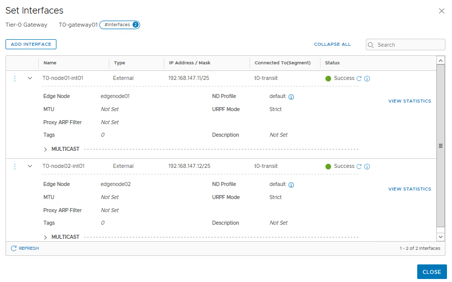
First, we have to configure the interfaces. Since we’re technically deploying two T0-gateways – one on each edge node – we need to configure two interfaces as well.
Go to the ‘Interfaces’ section and click ‘Set’.

As you can see, we have to configure the edge node this interface applies to. Also you can see here we use the t0-transit segment we configured previously.

Click ‘save’, then add another interface but connected to ‘edgenode02’.
HA VIP
Now we can configure an HA VIP. This allows us to use a single IP address to route ingress traffic. This is essentially HRRP. Click ‘Set’ next to ‘HA VIP Configuration’ in the top section.

Click ‘add HA VIP Configuration’, give in an IP and select the two interfaces we just configured.
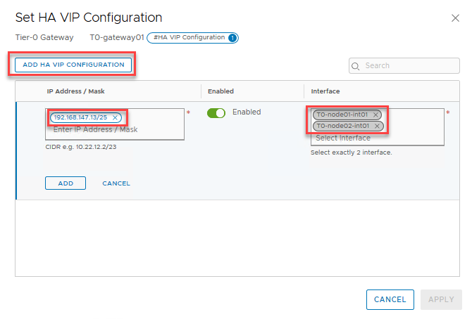
Don’t forget to click ‘add’ and then ‘save’ in the configuration!
Routing
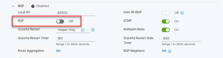
This is a simple lab, no need for dynamic routing. So I’m going to disable BGP in the respective section. BGP configuration deserves its own blogpost, maybe in the future! I’ll be sure to update this post when I get around to that.
Since we’ll be using a single static route for ingress from our “physical” (VYOS) router, and egress will be done through a default gateway, we don’t need to configure route-redistribution on the T0. Since this is outside of the scope of NSX-T I won’t show it here, but remember to configure this route, otherwise your traffic won’t be able to get into your environment! In my case I defined a route for 192.168.148.0/23 with next hop 192.168.147.13.
We do need to set a static route as a default gateway on the T0, so that traffic can find its way out. Go to the ‘Routing’ section and click ‘Set’ next to ‘Static Routes’.

Fill in our route of last resort ‘0.0.0.0/0’ and then click ‘Set’ in the ‘Next Hops’ column. This opens up a new window.

Click ‘set next hops’ and fill in the next hop, which is my VYOS pretending to be a physical router. Remember to click ‘Add Item(s)’ below the entry field!

Click ‘add’, ‘apply’, then ‘save’, and finally ‘close’ to go back to the T0 configuration.
That’s it for the T0, next up our distributed T1-gateway!
Step 2: T1-Gateway
The T1-gateway is responsible for our east-west traffic. Our segments will connect directly to this gateway, which in turn connects to the T0 upstream. Because we won’t be using any networking features we don’t need to have a ‘physical’, or service router, deployed. All T1 routing is done in-kernel in the ESXi host, much like the DLR in NSX-V.
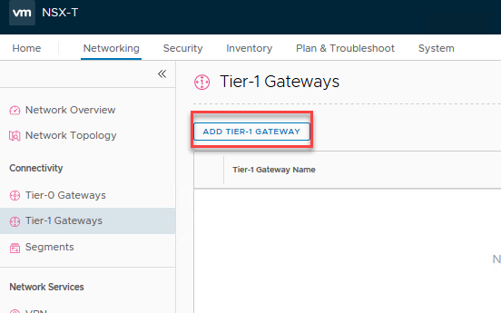
To deploy one, go to the ‘Networking’ tab, ‘Tier-1 Gateways’ and click ‘Add Tier-1 Gateway’.
Fill in a name, and select what T0 it must uplink to. Take note that we select nothing on the ‘Edge Cluster’ dropdown, because we don’t need that. If, in the future, I change my mind, I can simply select a cluster here and get the networking features anyway. No locked in decisions here!
A neat feature of NSX-T is the ‘route advertisement’ segment of the configuration; rather than defining BGP or OSPF or any other dynamic routing protocol, we tell the T1-gateway what routes or connections it should advertise upstream. In this case, we only have to enable ‘All connected segments & service ports’ to push the routes upstream. If, for example, I’d define a load balancer on this T1 as well, I would enable the options to the right as well.
As for a default route upstream from the T1; we don’t need to configure this as it is standard behaviour for a T1 to use the T0 as its default gateway.

After we click save, we’re once again asked to continue configuring, but we’re done with this one. Click ‘no’.

Take note that we didn’t need to define any interfaces! NSX-T uses a special feature I’ve heard being referred to as ‘auto plumbing’ to create connections between gateways, completely automagically!
On the ‘Network Topology’ tab we get a very awesome overview of the entire NSX-T environment we have created so far. We can see our T0-gateway with its 2 interfaces, and the auto plumbed interconnect between the T0 and the T1; 100.64.48.0/31. If you need to edit this subnet for some reason, you can do so in the advanced features.

And that’s it for the routing part of our NSX-T lab! We have everything setup to allow traffic in (route on VYOS), traffic out (default gateway on T0), traffic downstream (route advertisements on T1) and upstream (standard in T1).
Step 3: Segment
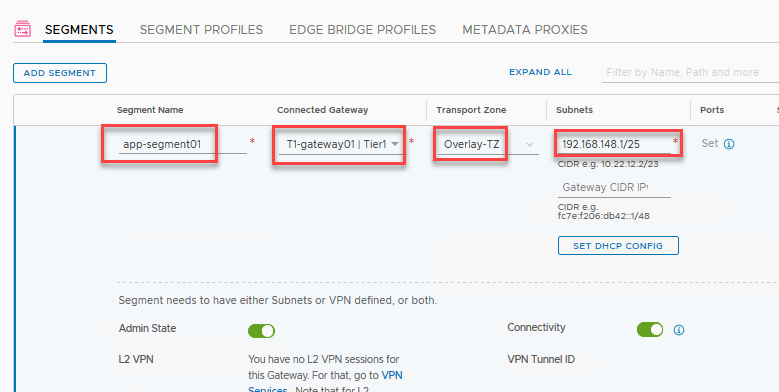
And the final part of our NSX-T endeavor; the NSX-T segments where our VMs will be connected. Go to the ‘Networking’ tab, ‘Segments’ and click ‘Add Segment’.
Here we give it a name, for example ‘app-segment01’, plug it in to our T1-gateway, and make it a member of the Overlay-TZ. Then we define the subnet and the interface IP at the same time. Since I’ve subdivided my /23 VM subnet into four /25 parts, the first being 192.168.148.1/25.
Click ‘save’ then ‘no’ when asked to continue configuring.

And now we have a segment we can connect our VMs to! It simply shows up as a regular portgroup inside of vCenter, so if we head over there and edit our VM’s network settings, we can click this segment to attach it.

After configuring the IP address in the VM itself we can verify connectivity!


Here you can see the following hops; the segment gateway IP (192.168.148.1), the downstream interface of the T0-gateway (100.64.48.0), and our downstream interface of the VYOS router, or the ‘physical’ world (192.168.147.1)!
Pinging towards the VM shows the upstream interfaces; first the outward HA-VIP interface of the T0-gateway (192.168.147.13), then the upstream T1 (100.64.48.1), and finally the VM itself (192.168.148.10)!

Wrapping up
And there you have it! A fully functional (lab) setup of NSX-T! All the way from installing the NSX-T manager and connecting it to vCenter, creating transport zones, profiles, and IP pools for all the different components, more profiles and edge clusters, and also some explanations of the different parts in the meantime, all the way to pinging our VM. Quite the ride!
As you can see, a lot of the work in NSX-T is the preparation. But all that prepwork pays off with the ease of maintaining and expanding our environment. It is very easy to manage, even when it grows in size. It took me a while to really appreciate NSX-T with its profiles, but I’ve grown quite fond of the direction VMware is taking this product.
Next post, we’ll take a look into getting some distributed firewalling to finalize this blog series!

In post 3, you mention a number of VLAN ID’s can you reference which IP subnets they correspond to?
Great series.
LikeLike
Hi Matt, sorry for the delay. I’ve added a table with all the VLANs and subnets to post 1 of the series, hope that helps!
LikeLike
Literally the first guide that got me to the promise land of a fully working NSX-T 3.1 CVDS fully collapsed cluster. Can’t say thanks enough. The only thing I would add is in the next hop section to spell out that the last resort route should be pointed to the gateway of the uplink/transit VLAN as at first I had just put in what the default gateway was of my lab (ie. 192.168.1.1). I quickly figured it out once I looked at the Network Topology in NSX-T but it caught me for a second.
LikeLiked by 1 person
I am bet confused, when we deploy Edge it comes with 4 NICs one of them connected to the VLAN VDS-PG in the Vsphere, and in T0 GW we can add 2 interfaces attached to segments type VLAN. so could you please clarify the differed between them?
LikeLike
Hi Ahmed Taha, the Edge Node indeed has the 4 NICs; 1 for management, and the other 3 are for GENEVE/VLAN. There are a few ways to configure these 3 interfaces, either as VLAN or as Overlay. I normally configure 2 of the NICs as trunks to carry both VLAN and Overlay traffic, as this makes the configuration a bit easier. The final one is reserved for bridging, so when you don’t use that it is unused.
The T0 Gateway interfaces are the routed interfaces for connecting to the physical network. So in my configuration the T0 interfaces go _through_ the Edge Node NICs, since they’re both Overlay and VLAN.
I like to think that the Edge Nodes are to (T0/T1) Gateways as ESXi hosts are to VMs: they are just boxes of resources that are consumed by the gateways. Much like the ESXi host has physical NICs through which the VMs communicate, so do the Edge Nodes through which the T0’s communicate to the outside world. It’s all about layers 😉
LikeLike
Hi, Robert thanks for an amazing blog. What I am having an issue with is that my segments cant access the internet.
I have my home lab and used vRouter (vyOS). I have a public IP configured on it and three vlans for mgmt, TEP & uplink. I’ve also used NAT for my mgmt & uplink VLANs. I can access internet on mgmt VLAN but on my segment. I am able to ping my Public IP on the Router (vyOS). but unable to go forward like cant ping google.com etc. can you let me know where I got it wrong?
LikeLike
Hi Moh AB, this can be a few things, it’s hard to determine which of these it is without digging into the environment. NAT is especially annoying in situations like these. I’d check out the following (not in any order):
1. Is there a default gateway configured? Does your VM go out based on default gateway, or is it routed? What about the T0?
2. Verify all the routing tables, to go your Edge Node, then into the vrf (get logical-routers, find the SR component for the T0, then get route). Also do this for your VyOS.
3. Tracerts tracerts tracerts!
4. Being able to ping the public IP on the router means you can traverse _through_ the T1, T0 and VyOS devices, which means that probably the objects beyond that have trouble finding your router back, so maybe its is related to NAT. I would do a packet capture on the outside of your VyOS to see if traffic exits from there, and of course if you get anything back.
5. Did you check DNS? 😉
LikeLike